Release news Naviate for Revit
Naviate Fabrication March release 3.8
Release news for Fabrication. Improvements includes Hanger and Trapeze Overhaul, Hanger and Point RFA Upgrade, Multi Service Hanger Array Configs, Trapeze Array Configs, Trapeze Over/Under Command, Trapeze Multi Tier Rack Command, Manual Strut Command and more.
-
Update
-
Update
-
Update
-
Update
-
Update
-
Update
-
Update
-
Update
-
Update
-
Fix
Please note: Naviate MEP and Fabrication are now available for Revit 2019 through 2025
Hanger and Trapeze Overhaul
This release includes enhanced Fabrication Hanger and Trapeze functionality with a revamped button palette layout and improved command workflows.
Hanger and Trapeze commands are now organized into separate dropdowns, each grouping their associated commands for improved usability. These dropdowns also include new features, which are detailed further on this page.


To access Hanger Configurations and Sleeve Options, click the slide-down button (1) at the bottom of the Fab Model palette. This slide-down will reveal the ‘Settings’ panel, which includes the new locations for the Hanger Array Configurations and Sleeve Options buttons. See below for more information.


Hanger and Point RFA Upgrade
The Naviate-provided Hanger and Point RFAs have been updated to version 3.8, with improvements to parameter naming conventions and geometry associations. Improvements are such that:
- In BIMrx_Hanger_Rack.rfa and BIMrx_Hanger_Round.rfa, correct the parameter names to BIMRX_Rod Height and not BIMrx_Rod_Height.
- In BIMrx_Hanger_Rack.rfa, associate the unistrut geometry to BIMRX_Unistrut Width.
- In BIMrx_Hanger_Round.rfa, delete unused parameter BIMrx_Anchor Height.
- In BIMrx_Hanger_Rack.rfa and BIMrx_Hanger_Round.rfa, Update Family Version parameter to 3.8.
Multi Service Hanger Array Configs
The Hanger Array Configurations command in version 3.7 of Naviate only allows one (1) Fabrication Service to be associated with a Hanger Configuration. In 3.8, you can associate multiple Fabrication Services to one Hanger or Trapeze Configuration.
For example, Plumbing Domestic Water can be split into three (3) subservices, Domestic Cold Water, Domestic Hot Water, and Domestic Hot Water Return. These three Services typically could share similar hangers. Instead of creating a separate Hanger Configuration for each of these three Services, you can create one Hanger Configuration and associate those three Services.

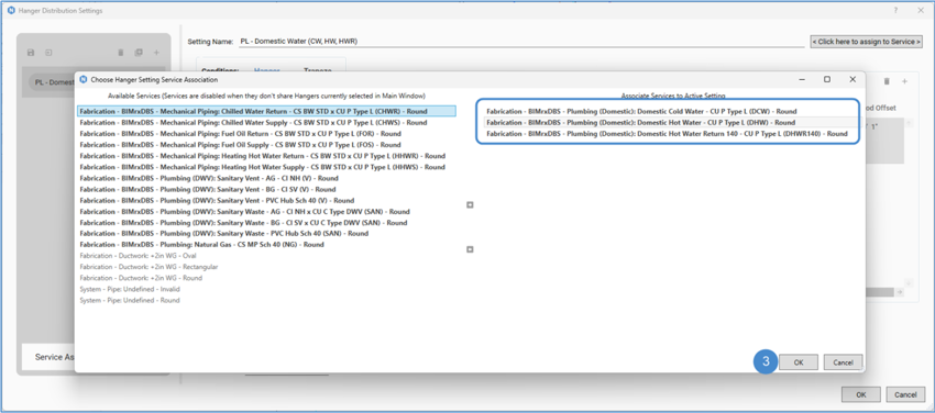
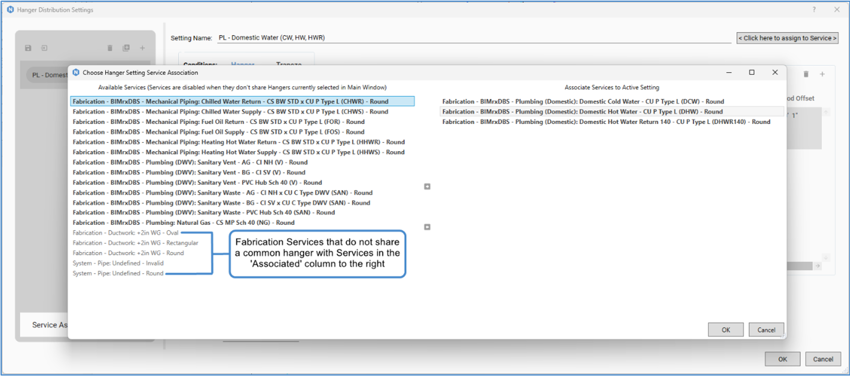
Please note that the tool allows you to add Fabrication Services that share at least one (1) common hanger with those in the ‘Associated’ column. As seen in the following screenshot, if Services have been moved to the ‘Associated’ column to the right, some Available Services on the left stay bold, meaning they share at least one common hanger. However, Services that turn halftone are unable to be added because they do not share common hangers with Services added to the ‘Associated’ column to the right.
Trapeze Array Configs
Similar to Hanger Array Configurations, this new feature allows you to set the same configuration settings for Strut-type hangers, which are hangers that span across and support multiple straight elements. You will see the separate Trapeze configurations can be set as shown in the following screenshot (1).

Please note that currently, the settings at the bottom of the Hanger Distribution Settings window (i.e. Distance from ends, Support before/after joints, Support before/after fittings, Attach to Structure, Place Point) will be applied to both Hanger and Trapeze conditions within one Hanger Configuration. Please see the following screenshot.

Trapeze Over/Under Command
This new feature is a modeling command that enables you to copy the same Trapeze hanger and hang it above or below an existing Trapeze hanger, inheriting the elevation of the chosen ITM above or below.

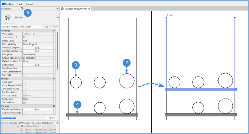
When started, the steps for executing the command are as follows:
- Select Trapeze Over/Under from the [N] Fabrication – Fab Model palette.
- Select the first element of new rack. This selection will be the starting point of the new trapeze hanger, establishing the elevation of the above/below supported element and the first point of the width.
- Select element for the opposite side of new rack. This selection will be the end point of the width of the new trapeze hanger. Note that you can select an element at a different elevation, since the elevation is established in Step 1.
- Select racks to hang from. This selection will be the existing strut-type hanger that will ‘host’ the new hanger. Multiple hangers can be selected.
- Click Finish.
The command will copy the host and place a new element, extending the new hanger’s rods to the top/bottom of the host hanger’s rods in a precise manner.
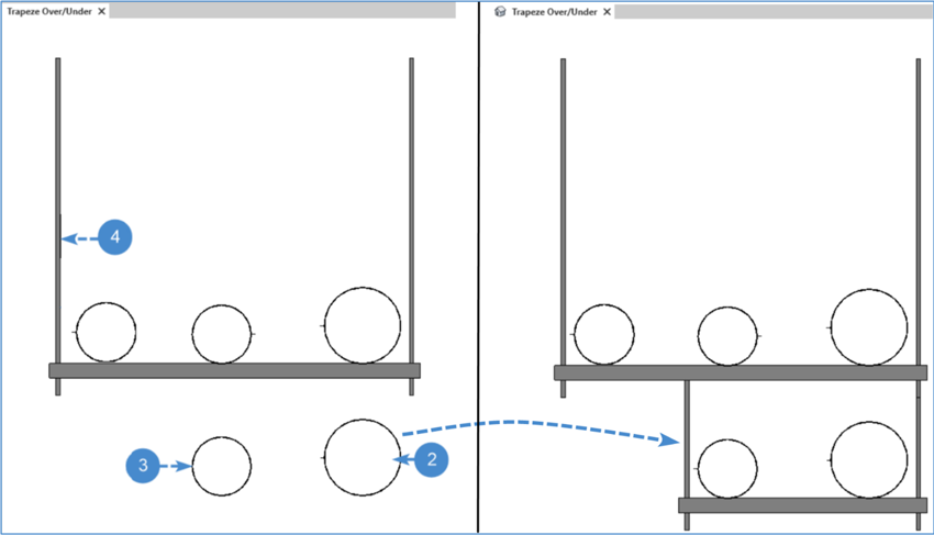
Trapeze Over/Under can also be applied in a condition where the existing hanger is at the top elevation and the new hanger is hung below. See the following screenshot showing outlining the same steps with a before and after result.
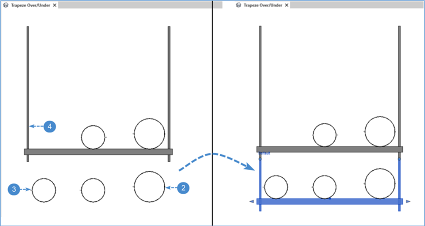
Lastly, Trapeze Over/Under can be applied in a condition where the new hanger is hung below with a shorter strut length. In the following screenshot, the rods extend up to the host strut in lieu of the plane of the host’s bottom rod.
Notes:
- Trapeze Over/Under can be executed in 3D, Section, and Elevation Views.
- At this time, Trapeze Over/Under is only compatible with Fabrication ITM Hangers.
- Trapeze Over/Under will apply Hanger Configuration settings as set up in the Trapeze condition.
Trapeze Multi Tier Rack Command
This is a new modeling command that enables users to add no-rod rack tiers to an existing Trapeze hanger, choosing the elevation based on the ITMs above or below.
The command can be operated with the existing host hanger either above or below where the new tier of rack(s) will be placed.
When started, the steps for executing the command are as follows:
- Select Trapeze Multi Tier Rack from the [N] Fabrication – Fab Model palette.
- Select racks to convert to multi tier. This selection will be the existing strut-type hanger that will ‘host’ the new tiers of racks. This trapeze hanger can be either above or below where the desired new tiers will be located. Multiple hangers can be selected.
- Click Finish.
- Multi Tier ITM Selection. This dialog will appear where you can select ITM Hangers in the active model’s Fabrication database via the dropdown list. Once a strut-type hanger is selected, press OK. Note that this hanger rack will be converted to a rack with no rods and placed in tiers that are defined in the next step. Further, the selected hanger is not required to be the same ITM as the hanger chosen in Step 2.
- Select straights to define new tiers. This is a selection of straights that will define what elevation the new tier racks will be placed. Select the straights and the new tiers will support at the bottom-of-pipe/duct/etc. elevation of the element.
The command will place new rack tiers and automatically convert the hanger to no-rod.


Trapeze Multi Tier Rack can also work in a condition where the existing strut-type hanger is at the top elevation tier (in a top > down condition). If new tiers are selected below, the existing hanger’s rods will extend down and move the strut at the lowest selected tier. New no-rod tiers are then added above. See screenshot below.


Notes:
- Trapeze Multi Tier Rack can be executed in 3D, Section, and Elevation Views.
- At this time, Trapeze Multi Tier Rack is only compatible with Fabrication ITM Hangers.
- Trapeze Multi Tier Rack will apply Hanger Configuration settings as set up in the Trapeze condition.
Manual Strut Command
Manual Strut is an advanced modeling command that allows users to place a selected Fabrication ITM Part as a simple strut by specifying the start and end points.
This feature is particularly useful for scenarios where modelers need to place surface-mounted struts on structural elements such as ceilings, floors, columns, or a Work Plane to support Fabrication ITM components.
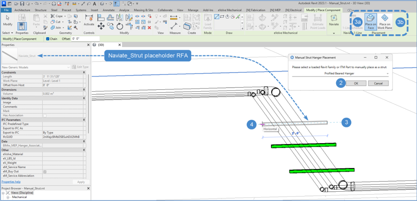
When the command is launched, a simple RFA called “Naviate_Strut” will be loaded into the model. This RFA acts as a placeholder that gives you visual preview feedback for the length, position, and elevation of the new strut hanger.
You will be first given the option to select an ITM Hanger to place as a Manual Strut. Once selected, Revit’s ‘Place Component’ mode will activate, allowing placement of the strut either by Place on Face or Place on Work Plane. When in placement mode, you will see the Naviate_Strut.rfa insert itself after clicking for the starting point. Once you click the end point of the strut, this placeholder will be converted to the selected ITM Hanger as a no-rod strut.
When started, the steps for executing the command are as follows:
- Select Manual Strut from the [N] Fabrication – Fab Model palette.
- Please select a loaded Revit Family or ITM Part to manually place as a strut. Select a Fabrication ITM Part that will be converted to a no-rod strut and placed in the model. Note: at this time, the dropdown list only contains strut-type ITM Parts in the loaded Fabrication database and two (2) Generic Model RFAs, BIMrx_Hanger_Strut and Naviate_Strut. Click OK.
- BIMrx_Hanger Strut – is the Naviate-provided RFA which currently would be placed with rods visible. This RFA could be used if the model does not contain compatible ITM hangers. The RFA can be modified by parameter values or in Edit Family in order to appear in the model as desired.
- Naviate_Strut – is the Naviate provided placeholder RFA that is used as a preview for length, position, and elevation during Step 3. You can also choose this RFA to place as the Manual Strut and adjust as desired in Edit Family if modification is required.
- Click to enter component start point. Revit will enter its ‘Place Component’ mode, where placement of the strut can be executed by Place on Face or Place on Workplane.
- Place on Face – Surface faces will highlight as you hover over different surfaces (i.e. of Category Floors, Walls, Columns, etc.). Note that the first click will be the starting point of the strut.
- Place on Workplane – The Options Bar will activate, allowing the Placement Plane to be chosen at which the strut will be placed. Placement Planes include Levels, Reference Planes, or can be selected with the Pick option. Note that in the Options Bar, you can Offset from the Placement Plane at a specified distance.
- Click to enter component end point. With Revit still in ‘Place Component’ mode, you will see the Naviate_Strut placeholder RFA as the sketch line, depicting a preview of the length, position, and elevation of the Manual Strut. The rotation angle as well as length of the Manual Strut are dynamic based on the cursor position. The second click will be the end point of the Manual Strut. The Naviate_Strut placeholder RFA will be converted to the element selected in Step 2.
- Repeat Step 3 to place another Manual Strut, otherwise press Esc to end the command.

When Placement is executed by ‘Place on Work Plane’, the strut can be placed on a selected Level, Reference Plane, or with ‘Pick…’ which is similar to ‘Place on Face’.

Notes:
- Manual Strut is currently only compatible with strut-type Fabrication ITM Hangers. Naviate provides two (2) RFAs: BIMrx_Hanger_Strut and Naviate_Strut that also can be placed as Manual Strut. These two RFAs could be adjusted in Edit Family for any customization if the Reference Plane and dimensions do not change. BIMrx_Hanger_Strut currently will display its rods as visible.
- Manual Strut will snap to the orthogonal directions in the X-Y plane after the starting point is established in Step 3.
- Manual Strut will convert the ITM Hanger to a no-rod hanger.
- MEP Hanger Updater, which is a Naviate Updater, must be enabled in order for Manual Strut to execute. This Updater can be found in Naviate Fabrication Settings in the Updater Toggle Panel tab.

Kick 90, Reroute Around, Reroute Under/Over
These features introduce new routing commands that automatically place elbows at user-specified angles to complete offset connections for Fabrication Parts. Previously exclusive to Naviate MEP for Revit System Family elements, these commands have been redesigned for compatibility with Fabrication ITM Parts.
Kick 90 allows you to choose the angle elbow that will be placed in combination with a 90-degree elbow to offset two intersecting MEP Straights at different elevations.
Reroute Around adds a ‘saddle’-type offset around a potential clash element at a specified angle, without changing elevation.
Reroute Under/Over adds a ‘saddle’-type offset under or over a potential clash element at a specified angle, by changing the elevation (a negative offset value will go beneath the element, and positive going above the element).
Data Sync
Previously only in [N] MEP, Electrical, and HVAC, this feature allows you to synchronize selected parameters between 2D Detail Items and 3D Family Instances.
Fixes
- Fabrication Routing
- Resolved various issues regarding tools not running for stacked elements, buttons in the Revit's Fab palette with no Part associated. Added warning message noting Fab Routing some tools are currently not supported for Fab Oval Duct.
- Spool Manager
- Resolved a crashing issue when Spool is renamed.
- Sleeve Options
- Resolved a crashing issue when no Shared Parameter file is loaded and/or importing Sleeve settings.
- Hanger Rod Extension
- Resolved an issue with Attach To Structure option not working with RFA Hangers.